
How Can We Help?
Subroutine: Modbus Master RTU for Read Holding Registers, Read Input Registers and Write Holding Registers
This Modbus Master subroutine is very useful if you wish to use our incredible ACE PLC for read or write in a Modbus RTU Slave devices.
If you want to connect the ACE PLC to a variable frequency drive, an intelligent sensor, a simple display, remote I/O or even an ACE PLC !
This subroutine allow you to:
- Read Holding Registers – Function code 03
- Read Input Registers – Function code 04
- Write Holding Registers – Function code 06
You can download the subroutine with its example here.
Beware, this Modbus Master is not as fast as a native Modbus Master. Watch this video to get an idea.
We poll 8 Modbus slave temperature sensors on the RS485 network. (ACE-1430)
How does the Modbus Master subroutine work?
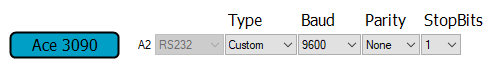
Your ACE PLC must be configured as Type = „Custom“ serial port.
Import in your project the 2 subroutines via the „Add Subroutine“ button :
- MBCRC16
- ModbusMaster

Define your Modbus requests to read and write data. It is very important to read the data first and then write the others.
In our example, we want to read and write this Modbus registers:
| Number “ n “ of the Modbus Request | Slave ID of the Modbus Slave Device SlaveID[n] |
Read or Write in the register ? FunctionCode[n] |
Address in the Modbus register ? Register[n] |
| [0] | 01 | 03 (Read Holding Registers) | 00 |
| [1] | 01 | 03 (Read Holding Registers) | 01 |
| [2] | 01 | 06 (Write Holding Registers) | 02 (We write in 65432 in our example) |
| [3] | 01 | 06 (Write Holding Registers) | 03 (We write in the tag „ValueMove“ in our example) |
We use a array of „n“ elements for each parameters
Setup these tags:
If, as example, you have only 3 registers to read/write, you can adjust the array from 16 to 3.
|
  |
| Now, you can complete your array with the 3 values for each Modbus request:
We start with n = 0
and next… n = 1
… < ! > Important: The last line must be SlaveID[n+1] = 00, in our example SlaveID[4] = 00
|
 |
| And just add now the ModbusMaster subroutine !
You must call this subroutine at each PLC cycle. |
 |
You will retrieve your data in the Data[n] array.
If you use the write function, do not forget to enter the value. In our example, we write 65432 in Data [2] and the value of another „ValueMove“ tag in Data [3].
