
How Can We Help?
Digital inputs: How to wire digital inputs
How to wire digital inputs?
The Ace PLC can interface any DC voltage signal between 3 and 30 VDC. Typical system designs utilize 5 V, 12 V or 24 VDC.
- Any connection to DC voltage between 1.5 and 30 VDC is sensed as a ‘1’.
- Above 2.2 V, it is guaranteed to be a ‘1’
- Any connection to ground (or voltage below 1.5 VDC) or an open connection is sensed as ‘0’.
- Below 0.8 V, it is guaranteed to be a ‘0’
- The ground reference of the signal must be connected to the ground terminal pin next to signal 1, or to the PLC’s input power ground.
- ACE digital inputs are NPN transistor inputs. NPN Inputs = Positive logic.
- The last pin on each digital input port connector provides a voltage (connected to the 5V power input, through a 10 ohm resistor and a diode) which is used by the Optocouple Input Terminal modules. It can also be used to supply “wetting voltage” to dry contact inputs.
- Internally, as part of the protection circuit, each digital input is pulled to ground through a 10K ohm resistor. This pull down resistor ensures that the digital input shows up as inactive when nothing is connected or the connection just sources voltage when it is active.
The logic is the following:
- When the INPUT is linked to VDC (+), the input = 1
- When the INPUT is not connected to anything or the voltage is less than 0.8 VDC, the input = 0
Your sensor (here, the dry contact) must be connected to:
|
|
The ACE inputs are connected:
|
|

(+) is not used or only for dry contacts. It comes from the 5V, through a 10 ohm resistor and a diode. It is current limited (by the resistor) and is nominally 4.3V
- VDC (+) is the + of your power supply. From 3 to 30 VDC.
- GND (-) is the – of your power supply.
- (+) it is often the last pin of your connector
- (-) it is often the first pin of your connector
- INPUT is an input of your ACE PLC
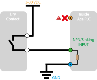
How to wire the input to a dry contact (Push button, relay contact,..)?
with a external voltageNothing on the (+) of the ACE PLC!
|
with voltage provide by the ACE PLCDo not use this 5 VDC to power anything
|


How to wire the ACE input to an encoder or sensor?
PNP sensor
|
NPN sensor
|


Read more: What sort of typical digital input signals that may be connected to the ACE digital inputs?
|
 |
Mechanical contact bounce
ACE digital inputs and the ACE CPU are very fast. For a small program, the logic scan and input scan can occur 5 times per millisecond. At this rate, mechanical contact bounce can signal the program that an input is changing rapidly – which can be a problem.
| To remedy this situation, vBuilder has an option to allow you to filter the digital inputs.
Note that debounce does not apply to inputs configured as high speed pulse counter inputs. |
High speed pulse counters
Using vBuilder, 3 high speed pulse counters can be configured for:
- basic high speed pulse counting (one digital input)
- quadrature pulse counting (two digital inputs)
The same signal level requirements apply, as listed above.
Digital AC signals inputs: 24 VAC or 120 VAC
For digital inputs that are AC signals, the ACE’s digital input ports can be connected to Velocio Optocoupled Input Terminal Block modules.
A cable, supplied with each terminal block module is then connected to the ACE digital input port.
The Optocoupler Input Terminal Block modules convert the AC signals to the proper DC levels to the PLC.